AUTOMATED MILLING MACHINE ASSEMBLE LINE
The duration of this project was approximately 3 to 4 months. There is a belt conveyor which helps to carry an object in front of to the CNC milling machine, then there is a push system which going to help to push the object on to the work bench of the milling machine and after the milling procedure is done, that machined part need to drag back on to the belt conveyor and it start moving.
This project contains 11 main steps:
1) First operate the belt conveyor motor to start moving the belt, fixtures are place on the belt. Fixture holds the object which is going to be machined.
2) Stop the belt conveyor motor at the proper position (right in front of the milling machine).
3) After that operate Motor No 1 of the push system to rotate the push system handle to fix the pusher and fixture together.
4) Then operate Motor No 2 of the push system to push the fixture on to the milling machine workbench.
5) Again operate Motor No 1 of the push system to rotate the push system handle, to release the pusher from the fixture.
6) Lock the fixture on to the milling machine work bench.
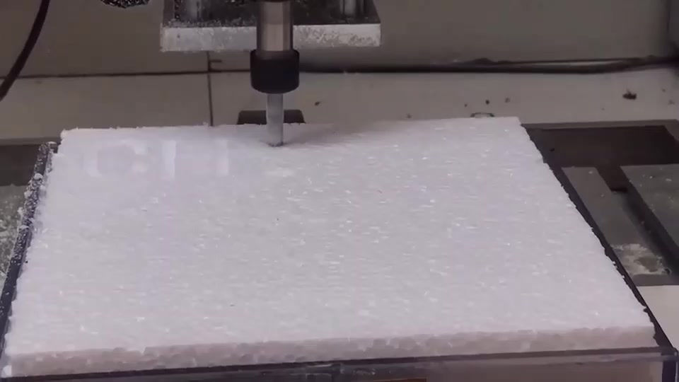
7) Starts the milling operation.
8) Then after the milling operation done, again have operate Motor No 1 of push system to rotate the push system handle, to fix the pusher with fixture.
9) And then operate motor No 2 of the push system to pull the fixture on to the belt conveyor.
10) After that Motor No 1 of the push system to rotate the push system handle, to release the pusher from the fixture.
11) Now belt conveyor starts moving again till the next part come in front of the milling machine.

The Design of Push system
The design has two main sections
This push system consists of 2 main parts. One is the Linear Motion part and the other part is Rotational Motion part
Leaner Motion section of Push system.
Actually the purpose of Leaner Motion section of Push system is to push the Fixture into the Milling Machine Bed and take it back on to the belt conveyor.
Rotational Motion section of Push system.
The purpose of this is to make the connection between the fixture and the rotational section of the Push system. There is a little part at the end of the Rotational section of the Push system which help to hook (attach) with the slot at the top surface of the Fixture.
Basic components of the Push System.
Two Stepper Motors. (One for Linear Motion and the other one for Rotational Motion.
Linear Motional part of the push system.
Rotational Part of the Push system.
One shaft coupling.
Stud with 20cm diameter.
Nuts with 20cm diameter.
Washers with 20cm diameter.
Base plane and front plane of the Push system.
Rotational section of the Push System
basic design
This is use to Push the Fixture from belt to Milling Machine Work Bench.
This is also made of PVC because metals are heavy and they expensive.
At the Edge of the long Rod there is a small piece of plate, which is going to help to lock and unlock the Fixture with Push System.
There are two circular holes in the Top and Bottom surfaces of the box, which help to place the stud into here. That stud fix with the stepper Motor with the help of Coupling.
This is glue I used to Put those PVC plates together and make that Push system Rotational Part.

The Belt Conveyor System.
The basic components
One belt.
One Stepper Motor.
Two Pulleys.
Four Side supports.
8 Bolts and 8 Nuts with the diameter of 12 centimeters.
16 Washers with the diameter of 12 centimeters.
One shaft coupling.
Base plane of the Conveyor system.
Base plane of the stepper motor.
Design of the Belt.
I used a homemade belt which is a flow carpet because buying an industrial conveyor belt is really expensive. I cut the carpet into 20 centimeter wide long pieces and take it to the tailor and put all the pieces together and complete the belt.
I could have use a bed sheet as the belt but it’s not quite strong so left that idea and I could have use a denim trouser but it's bit expensive so forget that idea too.
Belt Conveyor Motor
J-5718HB6401 machine height 112mm twist Moment 3.6N.m current 4.0A/3A axis diameter of 8/10mm, D shaft; axis length 20mm/25mm; lead length 50cm
Default delivery axis diameter 8mm, axis 25mm, lead length 50cm, electrical characteristic parameter Electrical Parameter.

Milling Machine
Milling Machine contain with
4 Stepper Motors.
3 shaft Couplings.
3 spherical shafts.(each one for each axis)
4 Bearings.(2 for each spherical shaft)
Aluminum Bench.
Aluminum body.
One shaft coupling.
Base plane of the Milling Machine.
One Power supply.
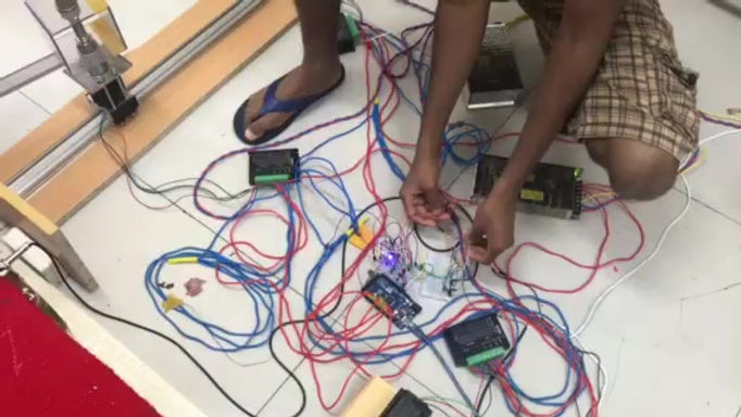
One Adriano circuit.
Chuck and Cutting Tools of the Machine.
Design of the Fixture.
The purposes of the Fixture to place the cutting object (Styrofoam).
This is made of PVC because metals are heavy and they are expensive.
Upper side of the bottom surface there are 2 parallel plates which helps to lock and unlock the Fixture with Push System.
The Bottom surface the Fixture there is a special kind of slot which help to fix the cutting object on to the base plane.
G codes to operate the Milling Machine.
For the whole system C language code file is attached.

Push the part on to the Milling machine.

Milling machine starts it's operation

Milling machine finishing it's operation.


